When connecting external digital devices to the iD44, its important to ensure that all devices are operating in sync with each other.
To ensure this, one device in the setup must be set as the master clock. The other devices will then use the master clocks signal to stay in sync. There can only ever be one master clock present in a chain.
The master clock signal can be sent either via an Optical cable embedded into the digital signal data, or through a BNC clock line cable. Please bear in mind that the clock will only travel in one direction through these conenctions, from a devices output to a devices input.
Choosing a Master Clock
Choosing the master device is usually very flexible. Quite often the best device to set as the master is the one that is connected to the computer (where possible) such as an audio interface. This way, when you open a project in a DAW, the audio interface should change to match the project sample rate, and therefore change the sample rate of all the slave devices. However this depends on the devices being used.
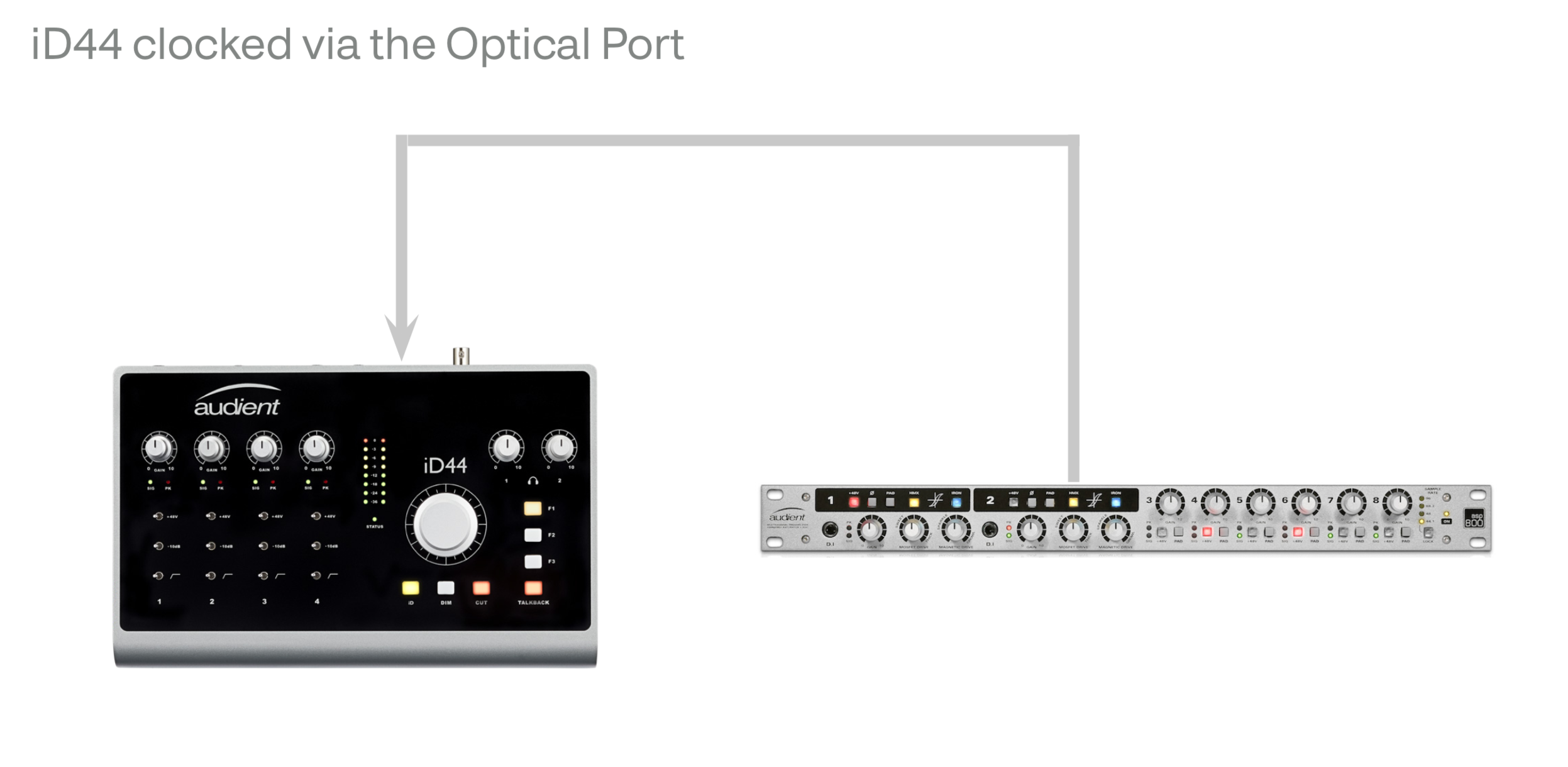
iD44 as the Master Clock
With the iD44 set as the Master Clock the other devices in the chain can be clocked by either the Optical Port or the BNC word clock output. When clocking just one device, clocking via the optical port would be the simpliest option, simply connect the TOSlink cable up to the iD44’s optical output and to the other digital devices input.
Then set the other device to Slave off the iD44’s clock.
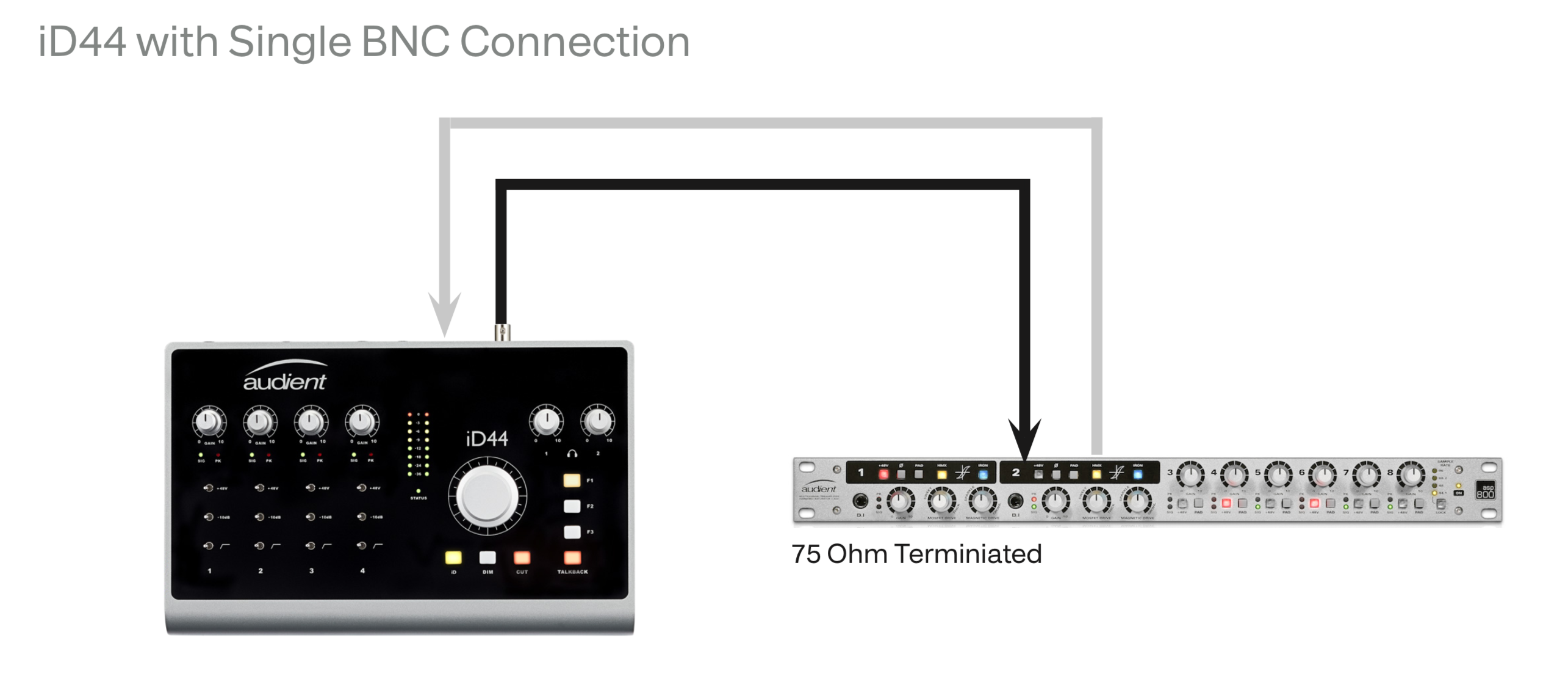
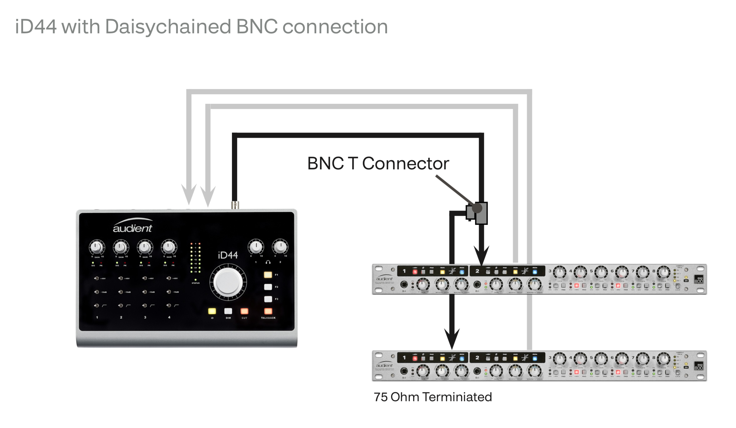
If you are using multiple devices then it is reccomended to use the BNC word clock output and then use T-connectors to Daisy Chain the Devices together. It is important to note that the final device in the chain has its BNC connector terminated with 75 Ohms to stop reflections of the clock signal. This should be an switchable option on most devices.
iD44 as the Slave
The iD44 can also act as the slave to an external master clock. The iD44 can only accept an external clock signal though its optical inputs, the BNC connector is an output only.
In this case, you would simply connect the the optical output of a device to the iD44’s Optical input. Then, in the iD mixer application, select the optical input you wish to be used as the clock source. You would also need to set the inputs to either ADAT or S/PDIF depending on the specification of the external device.